User-centred design — Involve relevant users when defining needs, generating ideas and evaluating models. Design for observed tasks rather than assumptions about an average person. Collaboration adds perspectives, but roles, evidence and decision making need to be clear. Respond to useful criticism rather than merely collecting approval.
Iteration and fixation — Iterative design cycles through ideas, models, tests and changes. Generate genuinely different approaches to avoid fixation on the first solution. Record what a test showed, the change made and its effect; repeated redrawing without new evidence is not meaningful iteration.
Systems approach — Break a complex proposal into inputs, processes, outputs and interfaces. Test sub-systems before integration, such as sensing, control and mechanical movement. Check how changes affect the whole: a stronger motor may need a larger supply, stronger supports and additional protection.
Models and prototypes — Card models explore size and form; a toile tests garment fit; a breadboard tests an electronic arrangement. A functional prototype demonstrates selected requirements but may differ from commercial production. Explain what the model can and cannot test before drawing conclusions from it.
Prototype evaluation — Test against justified specification criteria and collect appropriate user feedback. Use measurements and repeatable conditions, recording limitations and failures honestly. Suggest changes and retest; a prototype can be attractive yet fail stability, comfort, safety or marketability requirements.
Communication
Freehand and perspective — Sketches quickly explore form and annotate reasons. Isometric drawings use three axes with verticals and receding axes conventionally at 30° to horizontal. Perspective drawings use vanishing points to represent visual depth; they are less suited than dimensioned working drawings for exact manufacture.
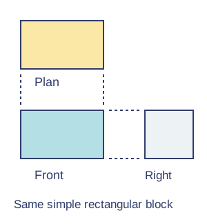
Orthographic drawings — Third-angle orthographic drawing aligns views: plan above front and right-side view to the right. Use appropriate line conventions, dimensions, units and scale; dimensions give actual intended sizes rather than measured print sizes. Include the projection convention so makers interpret views consistently.Third-angle view placement. Original schematic; apply the qualifications in the explanation.View full-size diagram
Exploded and schematic views — An exploded drawing separates components along assembly directions to reveal relationships, not to show their normal distances in use. A schematic uses symbols and connections to explain a system. Labels, a key and component identifiers make the communication usable to another person.
Digital and mathematical models — CAD enables accurate editable drawings and models; CAM uses digital data to control manufacture. Check units, toolpaths, material and machine limits before production. Mathematical models can estimate loads, dimensions or costs, but assumptions and measured validation remain necessary.
Recordings and annotations — Photos, video or audio can record testing and user responses with appropriate permission. Annotate the actual decision, reason and evidence. A gallery of unlabelled images does not explain development; choose communication that another designer or maker can understand.
Material management and safe making
Materials and tolerance — Select materials/components for the task, their working properties and the available processes. State allowable dimensional variation and compatible fits; over-tight tolerances can raise cost. Check safety-critical requirements through suitable supervision and tests rather than lowering them to fit available tools.
Planning manufacture — Plan a logical sequence with quality checks, stock quantities and realistic time. Mark from datums, use accurate templates/jigs/patterns and protect finished surfaces. Account for grain, kerf, seam allowances and nesting; a material area calculation is only one part of a usable cutting plan.
Process families — Wastage removes material through sawing, drilling or milling; addition joins or builds through soldering, welding, bonding, sewing or 3D printing. Deforming/reforming changes shape through folding, pressing, casting or moulding. Select a method for material, quantity, accuracy and available safe equipment.
Tool safety — Choose suitable tools and equipment and follow trained local procedures, guarding, extraction and protective equipment. Secure work and isolate equipment appropriately before adjustments. Never infer practical competence from a quiz answer; supervised making and inspection are part of learning.
Surface preparation — Clean, smooth or degrease as appropriate before applying compatible finishes. Protection against wear, moisture or corrosion and visual appearance can both matter. Follow material-specific application and curing guidance; an attractive coating can hide defects but cannot repair a weak structure.
Test yourself
30 questions · Random sets of 10. These quick checks support revision; practise longer explanations and justified judgements too.
Mind map
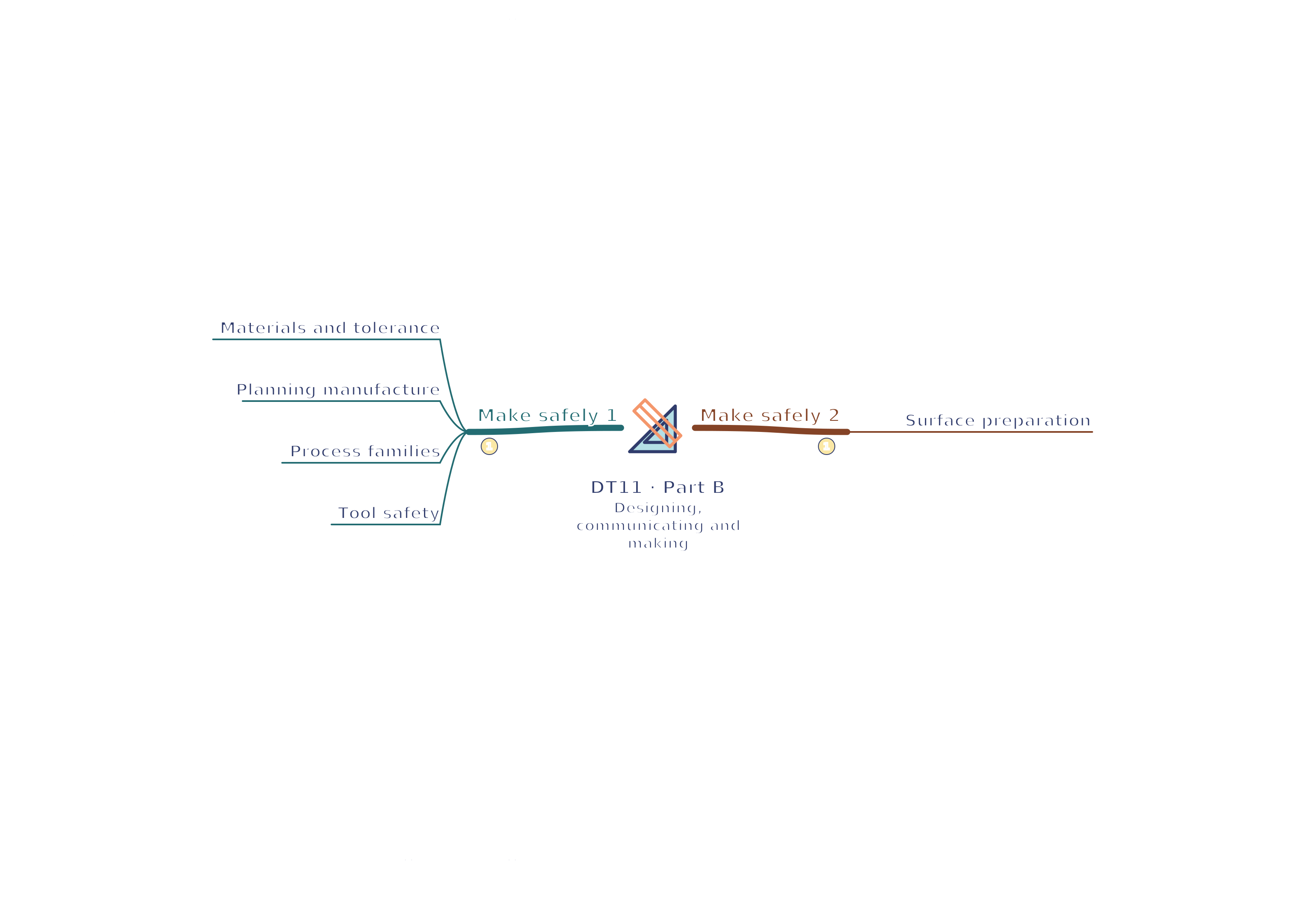
Use the branches to recall the ideas and explain their connections. Check the revision notes for the full detail.
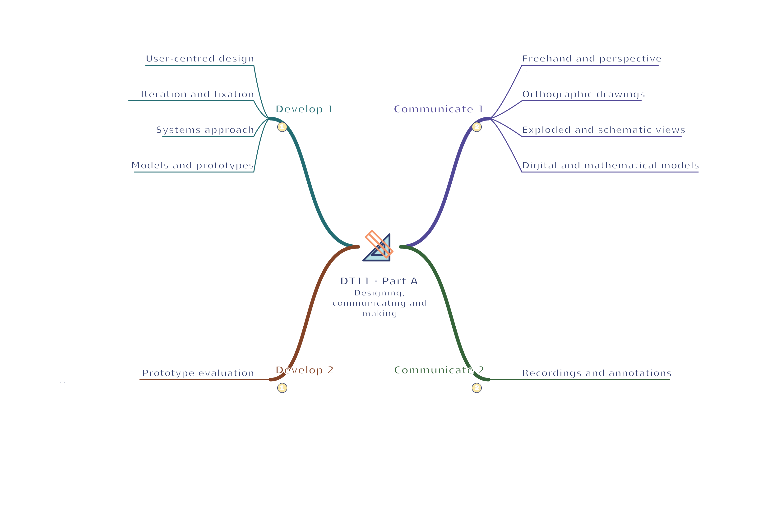
View DT11 · Develop 1 / Develop 2 / Communicate 1 / Communicate 2 mind mapOpen the full-size map to zoom. Download the PDF to print on A4 or enlarge to A3.
 Mr Kidman's Classroom