System selection — A domestic appliance or vehicle combines sensing, control, power and mechanical output. Specify the task, operating environment, voltage/current, torque/speed, dimensions and safety before selecting components. A component's low purchase price is only part of reliability and repair cost.
Resistors and sensors — A resistor limits current or forms part of a signal circuit; E12 is a preferred series of nominal resistance values. Tolerance gives permitted variation. Choose a sensor for range, accuracy and environment; an LDR or thermistor is not a complete controller by itself.
ICs and microcontrollers — A dual-in-line package has two parallel rows of pins; package shape does not specify function. A PIC is one family of programmable microcontrollers. Confirm pinout, supply and program before assembly; a library symbol alone does not prove an actual component is connected correctly.
Drivers and motors — A driver allows a low-power control signal to switch a larger output current. A motor needs a matched supply and mechanical coupling; starting or stalled current may exceed running current. Appropriate protection for inductive loads and faults depends on circuit design.
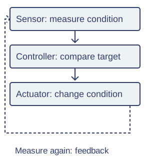
Feedback — Closed-loop control measures a relevant quantity and corrects deviation from a target. A room thermostat controls measured temperature; a motor speed controller can measure speed. Poor sensor placement, delay or excessive gain can lead to oscillation or inaccurate control.Closed-loop control. Original schematic; apply the qualifications in the explanation.View full-size diagram
Mechanical integration — Align shafts, gears and bearings and allow appropriate clearances. Friction produces heat and wear; lubrication suits the materials and operating conditions. Enclosures should protect moving parts and electrical connections while allowing necessary ventilation and access for maintenance.
Manufacture and assembly
Circuit prototyping — A breadboard permits temporary connections without soldering; know which holes are internally connected. Test a schematic section by section with a safe low-voltage supply. Avoid mains experimentation; teacher supervision and approved equipment are required for practical work.
PCB manufacture — A PCB provides conducting tracks and component support. Photosensitive board can be exposed through an artwork mask, developed and etched to remove unwanted copper. Exposure/development/etching times need control; chemicals, waste and UV sources require approved supervised procedures.
Drilling and soldering — Secure boards and drill appropriately sized holes where required. Solder wets clean suitable surfaces to make an electrical/mechanical joint; it does not glue any dirty materials together. Control heat, inspect joints and follow extraction, eye protection and hot-tool procedures.
Pick and place — Pick-and-place machinery positions components rapidly and consistently on boards. Flow or wave soldering passes suitable assemblies over molten solder; reflow soldering melts solder paste for suitable surface-mount assemblies. Component layout, heat profile and inspection remain necessary.
Mechanical fabrication — Cut, drill and assemble chassis parts from suitable stock with accurate datums and tolerances. Standard fixings and modular parts support repair. Deburr edges, protect wires from abrasion and check moving parts can travel safely without trapping or contacting the enclosure.
Quality, finish and footprint
Electrical testing — Inspect polarity, track separation and solder joints before powering. Continuity tests can detect an open connection or unintended short when used appropriately on an unpowered circuit. Then test expected and boundary inputs and outputs under safe conditions; continuity alone does not establish full function.
Finishes — Suitable PCB lacquer protects against some moisture/corrosion but must respect contacts and service needs. Anodising can improve aluminium chassis surface properties; lubrication reduces mechanical friction. A finish cannot replace insulation, grounding where required or physical guards.
Reliability and repair — Provide replaceable modules, accessible fixings and clear component identification. A sealed product can resist water but impede repair; judge the intended environment and safety. Use rated parts and realistic testing, documenting failure modes rather than promising permanent reliability.
Electronic footprint — Metals, polymers and electronic manufacture use energy and resources; mining and hazardous processing can affect workers and communities. Reduce standby consumption, extend life and use appropriate electronic waste collection. Separate batteries for their correct recovery route; do not put them into ordinary mixed waste.
Test yourself
30 questions · Random sets of 10. These quick checks support revision; practise longer explanations and justified judgements too.
Mind map
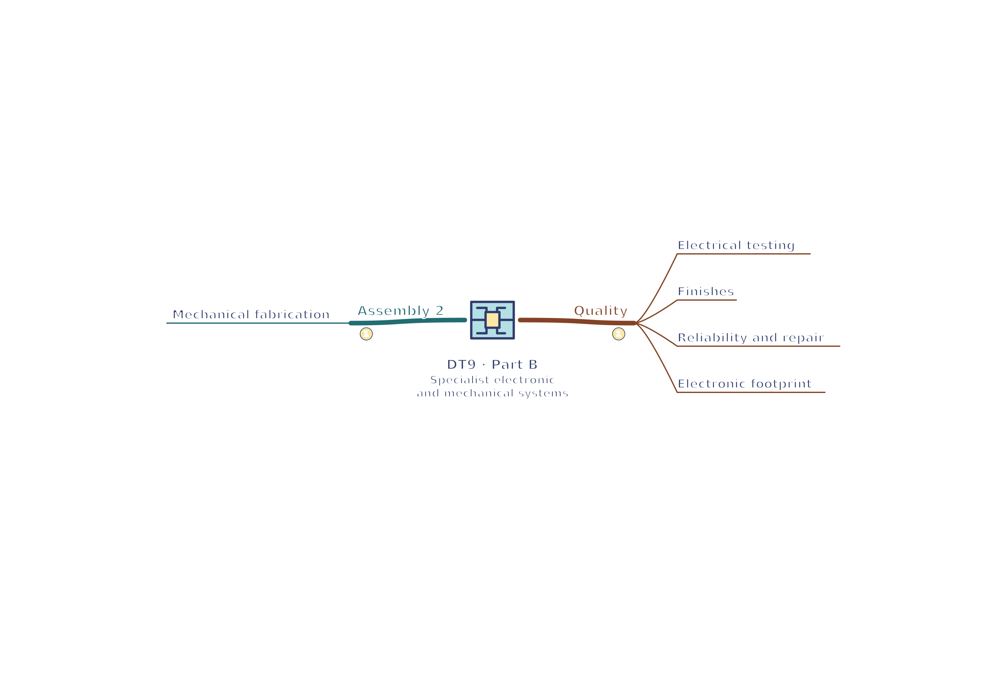
Use the branches to recall the ideas and explain their connections. Check the revision notes for the full detail.
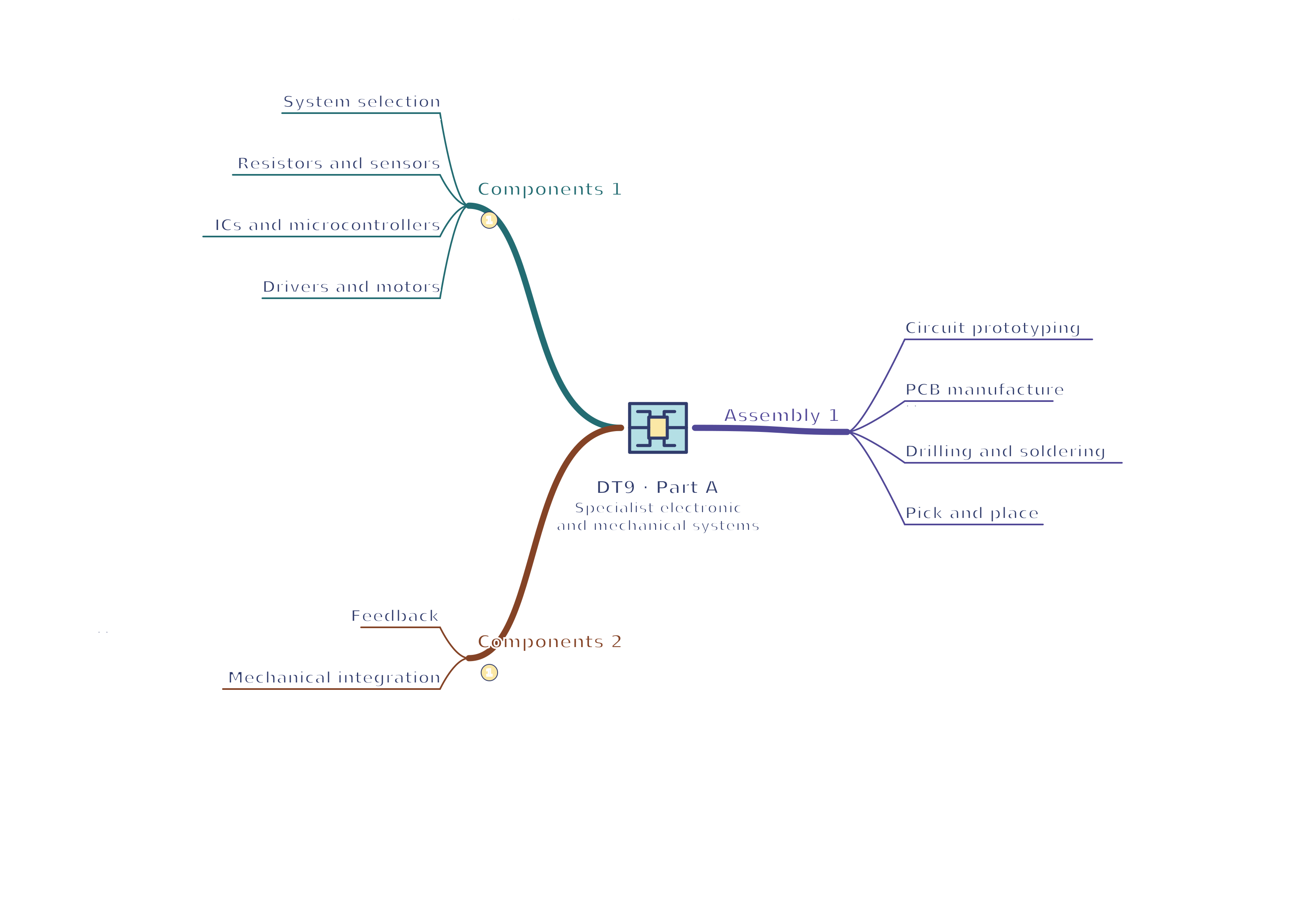
DT9 · Components 1 / Components 2 / Assembly 1
View DT9 · Components 1 / Components 2 / Assembly 1 mind mapOpen the full-size map to zoom. Download the PDF to print on A4 or enlarge to A3.
 Mr Kidman's Classroom