System model — A system has inputs, a process and outputs. A temperature sensor supplies an input, a controller compares it with a setting and a heater is an output. A block diagram explains function and signal flow; a circuit schematic describes electrical connections.
Input components — A switch gives an on/off input. An LDR changes resistance with light level, usually falling as light increases. A typical NTC thermistor falls in resistance as temperature rises. Sensors usually need an appropriate circuit to turn resistance changes into a useful signal.
Pressure sensing — A pressure sensor converts applied pressure into a usable signal, for example in a seat occupancy or fluid-pressure system. Select range, sensitivity and mounting from its technical specification. A switch may detect a threshold; continuous sensing can give more information but requires appropriate processing and calibration.
Processing — A microcontroller executes stored instructions to make decisions from inputs. It can apply thresholds, timings and logic, but needs power and correct programming. An integrated circuit combines many electronic components; it is not necessarily programmable.
Outputs — LEDs indicate status, buzzers produce sound and motors produce rotary motion. A controller output may need a transistor driver or relay for a larger load. Match polarity, voltage and current ratings; an LED normally needs current limiting.
Counters, timers and sound — A programmed controller can count sensor events, time an interval and compare input values to a threshold. Speakers convert an electrical signal into varying sound; buzzers often give a simple alert and lamps give light. Programmed functionality depends on the sensor signal, code and matched output driver, not the controller alone.
Control logic — An AND decision requires both conditions; an OR decision requires at least one; NOT reverses a condition. A door alarm can use door-open AND system-armed. Explain the actual conditions rather than memorising gate names without a context.
Open and closed loops — Open-loop control acts without checking the achieved result. Closed-loop control measures an output-related quantity and uses feedback to reduce error. A timed heater is open loop; a thermostat can control measured temperature around a set point.
Programming sequence — A sequence performs steps in order, selection chooses a branch and iteration repeats instructions. A flowchart can show sensor input, a decision and a motor output. Test expected, boundary and unexpected inputs before relying on a programmed system.
Motion and force
Motion types — Rotary motion turns about an axis; linear motion travels in a straight line. Reciprocating motion moves back and forth in a line; oscillating motion moves back and forth about a pivot. State both the starting and resulting motion when explaining a mechanism.
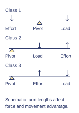
Levers — A lever turns about a fulcrum. Class one places the fulcrum between effort and load; class two places the load between them; class three places the effort between them. Force and movement advantages depend on arm lengths, not the class name alone.Lever classes: effort, pivot and load. Original schematic; apply the qualifications in the explanation.View full-size diagram
Moments — Turning moment equals force multiplied by perpendicular distance from the pivot. For a balanced ideal lever, clockwise and anticlockwise moments are equal. An effort of 10 N at 0.30 m balances 30 N at 0.10 m: both moments are 3 N m.
Mechanical advantage — Mechanical advantage is output force divided by input force. An ideal lever lifting 120 N with 30 N has MA 4. A greater force advantage is exchanged for movement; friction and deformation reduce useful performance in a real mechanism.
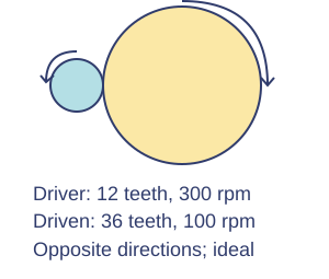
Gears — Meshing external spur gears turn in opposite directions. Gear ratio is driven teeth divided by driver teeth: a 12-tooth driver and 36-tooth driven gear give 3:1 speed reduction. Ideally the driven speed is one third and torque rises; friction reduces efficiency.Ideal spur-gear speed reduction. Original schematic; apply the qualifications in the explanation.View full-size diagram
Gear arrangements — An idler changes the final direction without changing the overall ratio between first and last gears. A rack and pinion converts rotary motion into linear motion. A worm and wheel provides large reduction; many arrangements resist reverse driving but this depends on design and friction.
Pulleys and belts — A belt transfers rotation between separated shafts. An open belt normally gives the same direction; a crossed belt reverses it. Pulley diameters set speed ratio when slip is negligible. Belts can slip under overload; toothed belts reduce slip but require alignment.
Cams and followers — A rotating cam drives a follower according to its profile. An eccentric cam gives a smooth rise and fall; a snail cam gives a gradual rise and sudden drop; a pear cam includes a dwell. A spring or gravity can keep the follower in contact.
Linkages — A linkage uses connected bars and pivots to transfer or change movement. A parallel linkage can keep an output member parallel; a reverse-motion linkage changes direction. Clearance at joints, stiffness and pivot placement influence accurate movement.
Bell crank and push-pull — A bell crank is a pivoted angled lever that changes force/movement direction, often through 90°. Push-pull linkages transmit movement through connected members, such as a control rod. A rigid rod can transmit push and pull if adequately supported; a flexible cable usually transmits tension rather than an unsupported compressive push.
Crank and slider — A crank and connecting rod can turn rotary motion into reciprocating motion, as in a piston mechanism. The slider is constrained to a straight path. The same mechanism can be driven in the reverse direction where its geometry and forces permit.
Test yourself
30 questions · Random sets of 10. These quick checks support revision; practise longer explanations and justified judgements too.
Mind map
Use the branches to recall the ideas and explain their connections. Check the revision notes for the full detail.
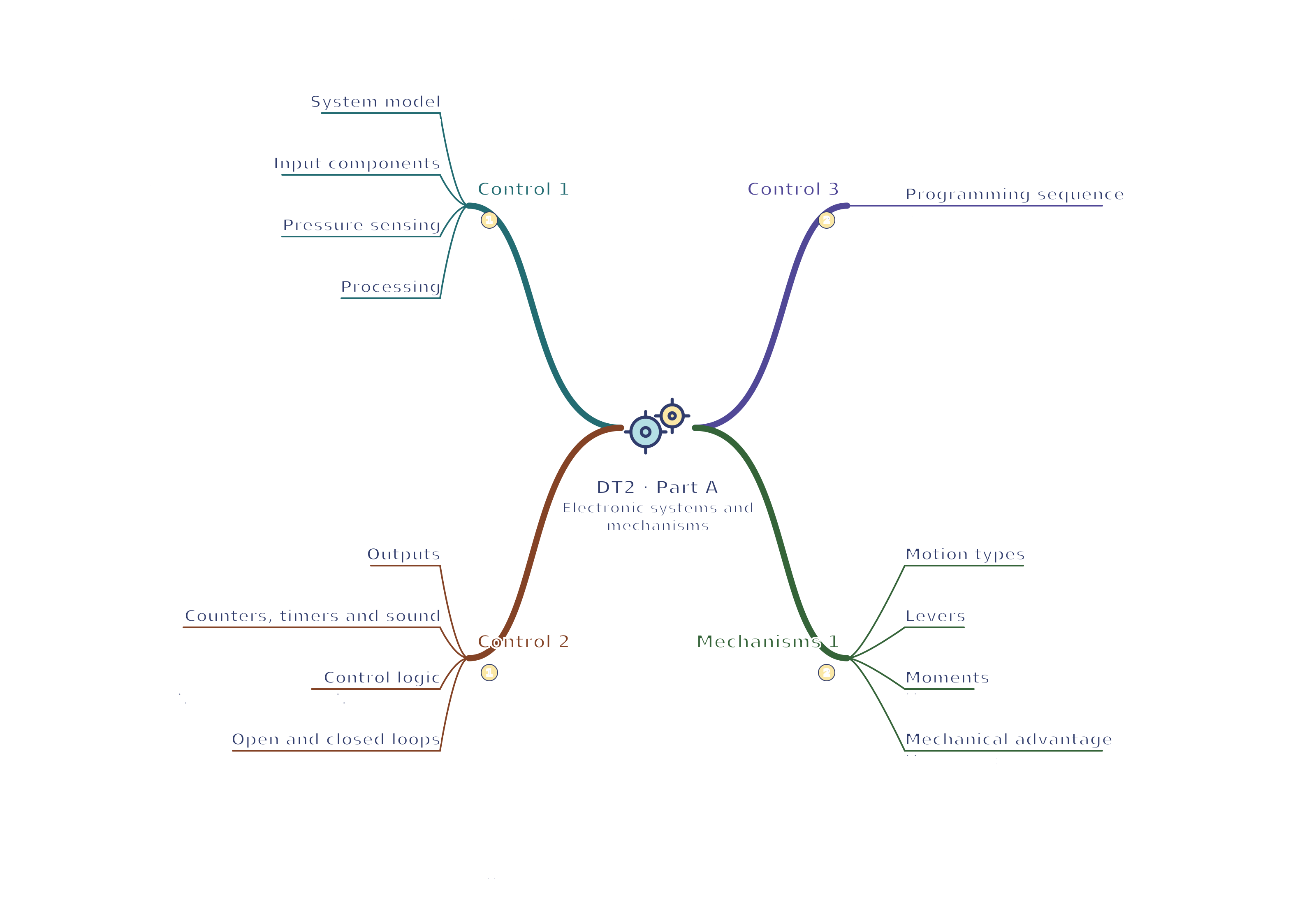
DT2 · Control 1 / Control 2 / Control 3 / Mechanisms 1
View DT2 · Control 1 / Control 2 / Control 3 / Mechanisms 1 mind mapOpen the full-size map to zoom. Download the PDF to print on A4 or enlarge to A3.
 Mr Kidman's Classroom